
Custom-made development - examples
Example of PCI Express, PCI and PC/104 add-on card
Since 1994 TEDIA® has been gaining experience with the development more than 100 types of PC add-on cards (ISA, PC/104, PCI and PCI Express). Moreover, in the years 2002-2016 TEDIA® was a member of PCI Special Interest Group.
PCI Express card - SpaceWire interface (2017)
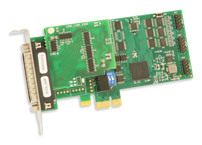
This interface PCI Express card was developed for BD SENSORS s.r.o., CSRC Space Division (formerly CSRC spol. s r. o., Czech Space Research Centre), an ESA audited Czech company.
The starting point of development was already existing "carrier" PCI Express card, however, the project required FPGA gate array with higher density and design of a new plug-in module.
The FPGA firmware is based on original ESA SpaceWire IP core (the card offers two independent interfaces), TEDIA® specialists added to this IP core powerfull PCI Express controller (works as a bridge between local bus and PCIe bus) and wide range of service circuit and features. Development tasks included also windows drivers.
Note: Please keep in mind, that the development of custom PCIe cards based on already existing "carrier" card can be realy economical way even for low batches.
PCI card - video signal generator (2005)
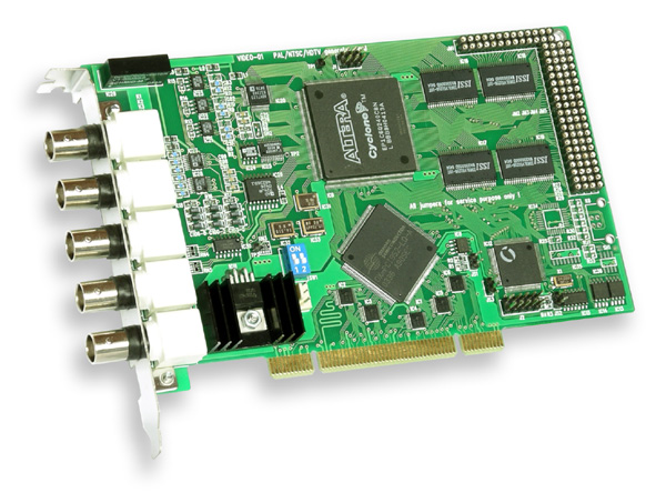
This special diagnostic card was developed for Panasonic AVC Networks Czech, s. r. o., a world-known manufacturer of audio and video electronic equipments.
The PCI add-on card provides the video signal generator, supporting the PAL, NTSC and HDTV systems, interlaced and non-interlaced modes and RGB, YUV, composite video or S-video output data. All signals are fully configurable (amplitude, frequency, ...), including generating a wide range of defects in signals.
The card is equipped with fast 8 MB memory, FPGA gate array for data processing (e.g. RGB to YUV conversion, brightness and contrast adjustment, color compensation, etc.) and output circuits providing fast 10-bit D/A converters, amplifiers and PAL/NTSC video encoder. The Windows drivers and the conversion utility (converts BMP, TIFF, PCX, GIF into internal RAW format in index or truecolor mode) were also developed.
Multifunctional PC/104 module for LVDS sensors (2014)
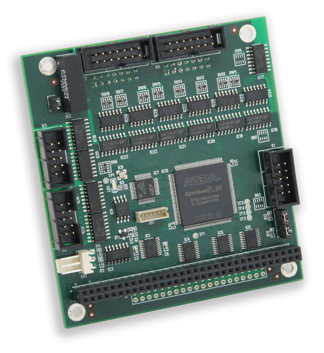
This multifunctional PC/104 module was developed for AMS Automation and Measuring in Industry, Ltd., a company specialized in the supply of measuring stations for dimensional inspection of electrical quantities devices for tightness testing for crack detection, marking inspected parts.
The module processes signals from up to 32 LVDT sensors using special measurement algorithms. The functional core of the module is based on FPGA gate array that provides all processing and signal generation LVDS sensors interface, synchronous sampling and data transfer using data FIFO buffers and PC/104 bus bridge.
User friendly upgrade of FPGA gate array firmware is provided by the on-board microcontroller.
Example of multifunctional USB modules
Multifunctional USB module for seismic monitoring (2010)
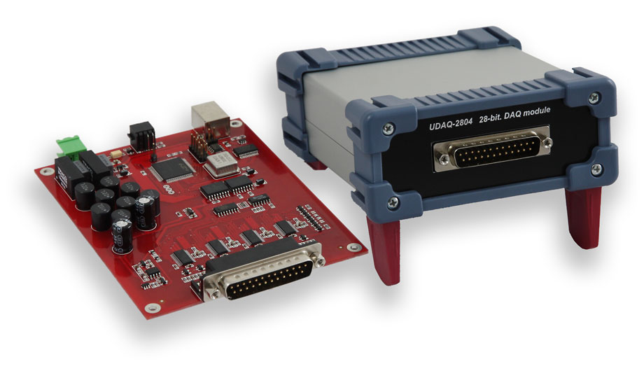
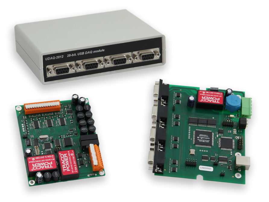
Two special USB modules for seismic measurement and monitoring was developed for the Institute of Rock Structure and Mechanics of the Czech Academy of Sciences.
The first module is a compact 4-channel module UDAQ-2804, providing four isolated channels and 31-bit ADC. The sampling frequency can be set in the range of 250 Hz to 4 kHz and the selectable input ranges are from ±40 mV to ±2.5 V. When the 250 Hz mode and ±1.25 V input range is selected, the achieved SNR ratio is better than -120 dB (SFDR). Moreover, UDAQ-2804 module allows to be synchronized with 1 pps timestamp from GPS receiver.
Another type is the 12-channel UDAQ-2812. Unlike UDAQ-2804 the electronics is divided into central unit (used as a data bridge between USB interface and four high speed serial ports) and four units providing analog inputs connected to the central unit using cables of the length of up to 100 m. Because the UDAQ-2812 circuit design comes out of the UDAQ-2804 module, the specifications are analogical.
Powerful USB measuring module (2013)
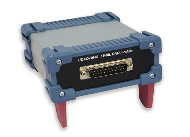
This powerful USB measuring module was developed for OZM Research, s.r.o., a leading company dealing with explosives testing instruments, detonation chambers and storage containers.
The UDAQ-3644 is equipped with four isolated analog inputs and 16-bit A/D converters with fully synchronous sampling frequencies up to 4x 800 kHz. Each input channel allows independent software calibration and voltage range selection from ±1 V to ±10 V.
Various boards based on middle/high density FPGA
Data Recording System (2013)
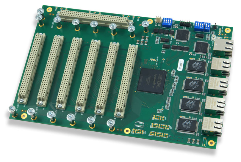
This custom-made electronic board is based on high density FPGA gate array and four gigabit ethernet PHY controllers.
The FPGA gate array firmware allows simultaneously receive data from up to 192 synchronous serial interfaces, process/select them and transfer via four gigabit ethernet interface to the (MAC layer is implemented in the FPGA gate array) into dataservers.
Maximal achieved effective data transfer rate of ethernet interfaces is more than 4x 100 MB/s when UDP mode is selected, or more than 4x 50 MB/s in TCP mode.
Standard LAN interface is used for configuration and system supervision.
Interface board for EEG/EP system (2011)
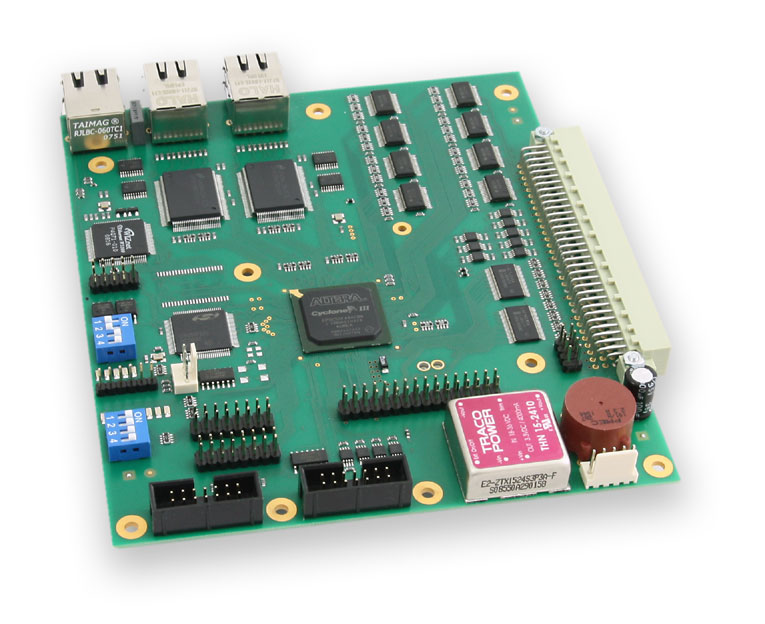
This custom-made electronic board was developed for M & I, spol.s r.o., a supplier of BrainScope system for recording, analysing and archiving of EEG/EP.
The board is based on middle density FPGA gate array, two gigabit ethernet PHY controllers, eight high-speed LVDS interfaces (up to 8x 40 MB/s, but 8x 10 MB/s as standard) and LAN for configuration and system supervision.
As the ethernet interfaces operate in UDP mode, maximal achieved effective data transfer rate exceeds 100 MB/s per channel.
Industrial electronics built into 19" rack
Modular DA&C System EU-3000 (since 2007 to the present)
The modular DA&C system EU-3000 was developed during the year 2007. The TEDIA® company provided the hardware development including the development and debugging of the communication protocol and the firmware for particulal units; the software support at the PC side was realised by the INOVA company.
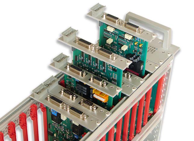
The DA&C system is currently based on one data concentration unit and set of I/O units built in the 19" rack with 3U height. The data concentration unit is designed as a central unit managing the timing of the whole system and the transfres between all I/O units and all PCs (up-to 50 kHz). Fast synchronous serial interface with the speed of 25.6 MB/s has been chosen for realizing the data transfer between the I/O units, the data transfer to the PC is realised through standard gigabit ethernet interface.
The DA&C system in full configuration allows the user to measure up to 480 analog channels and control up to 960 analog outputs or 1920 digital outputs using the currently developed units. The data processing of such amount of data can be distributed up to eight computers; every computer may obtain any subset of the input or output.
The I/O units are realized as standard eurocards (100x160 mm), connected to the rack control unit using special passive backplane providing 15 independent high-speed serial channels (one for every I/O unit).
Current product range of the I/O units provides measuring/control of:
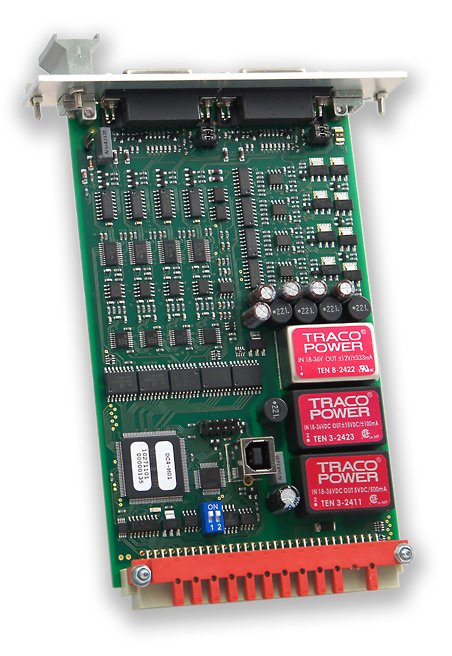
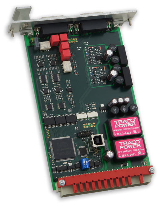
- analog inputs for DC bridges
- analog inputs for AC bridges and LVDT (based on high speed signal sampling and DFT post-processing)
- analog inputs for accelerometers
- general-purpose voltage analog inputs
- general-purpose voltage analog outputs
- analog outputs with current ranges up to 200mA
- bidirectional counters with quadrature encoders for IRC sensors
- configurable SSI master controllers
- isolated digital inputs
- relay power outputs
Compact measuring and control systems
Electronics for the gas concentration detection system (2004)

This control unit for the gas concentration detection systems was developed for KR Protect, spol. s r. o., a leading company dealing with components for detection of combustible, explosive and toxic gases and fumes.
The CS-484 module allows to track eight gas concentrations (via eight gas sensors) and to evaluate the measured data in the eight independent four-level alarm comparators with the feature of time delay and masking unused channels and levels. Alarm comparators are routed to five digital outputs built in the modules (can be extended up to 32 via RM-516 or RM-560 extension modules).
Each channel and each alarm comparator can be independently configured by software utility. Moreover, the latest version of the software was enhanced with PEL features (exposure limit values, the calculation procedure is complying with EU directives).
For central processing, the unit is equipped with the RS-485 line with the Modbus protocol.
Boards for a special kind of electronics...
Programmable unit - production line monitoring (2015)
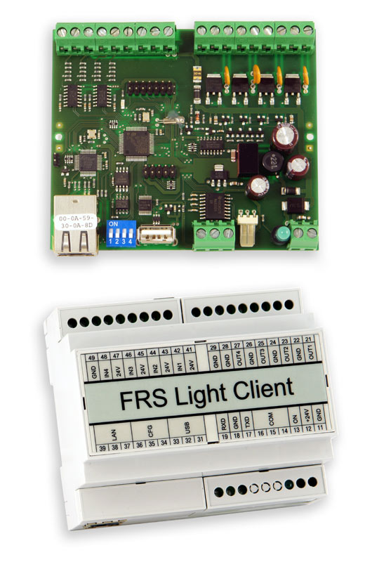
This programmable was developed on demand BOSCH company (Robert Bosch spol. s r.o.).
The electronic board (designed for installation in to DIN 35 mm rail mount box) is based on powerfull Cortex M4 microcontroller and contains standard LAN interface (communication with server), USB host port (configuring and updating firmware from a USB flashdisk), two serial lines (communication with other devices) and several digital I/O ports (up to four buttons and four signaling elements like indicator lamp or signal tower).
Installed software allows to monitor the operating modes of production lines (ready for operation, malfunction, ongoing repair service etc.), responds to operator intervention and reports statuses to the central server. Programmable unit is also synchronized with server events.
External module for audio signal digitization (2005)
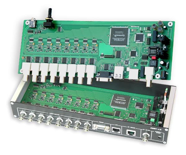
This special custom-made module was developed for the audio signal digitization.
The module allows to digitize up to eight audio channels in several modes from 8bit/8kHz to 16bit/48kHz and all inputs provide programmable gain amplifiers with the 0.5 dB steps.
The digitized signals can be transferred simultaneously using the RS-422 line with the baud rate of 2.048 Mbit/s or using the E1 G-703 interface. Ethernet interface can be also used for sending data from the selected audio inputs.
Moreover, dedicated RS-232 interface is available for the on-the-fly configuration.
GPIB + Ethernet + USB Interface (2002, 2003, 2005)
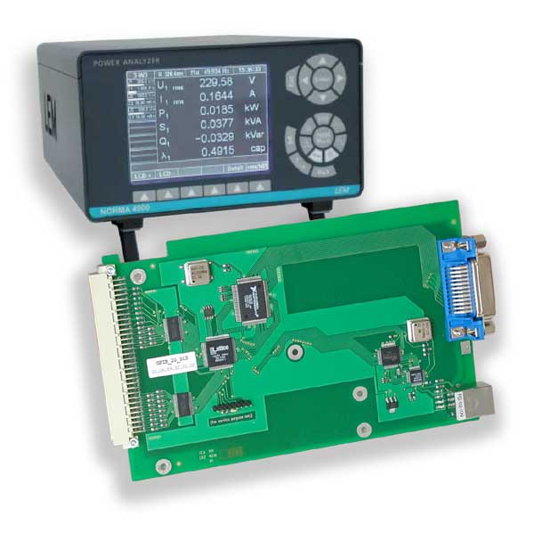
This interface board was developed on demand as a special inerface for the LEM Norma 4000 series (Austria), measuring equipments for analyzing of the electrical power system parameters.
The board provides the bridge between the microcontroller synchronous bus (Motorola MCF5307, 32-bit/36MHz; the main microcomputer of the equipment) and the local asynchronous bus of the GPIB controller. This bus-bridge based on CPLD gate array provides all data tranfers including features of both DMA and IRQ.
Next revisions of the board based on powerfull FPGA gate array integrate also Ethernet or USB interface.
Independent power protection for nuclear reactor (2005)
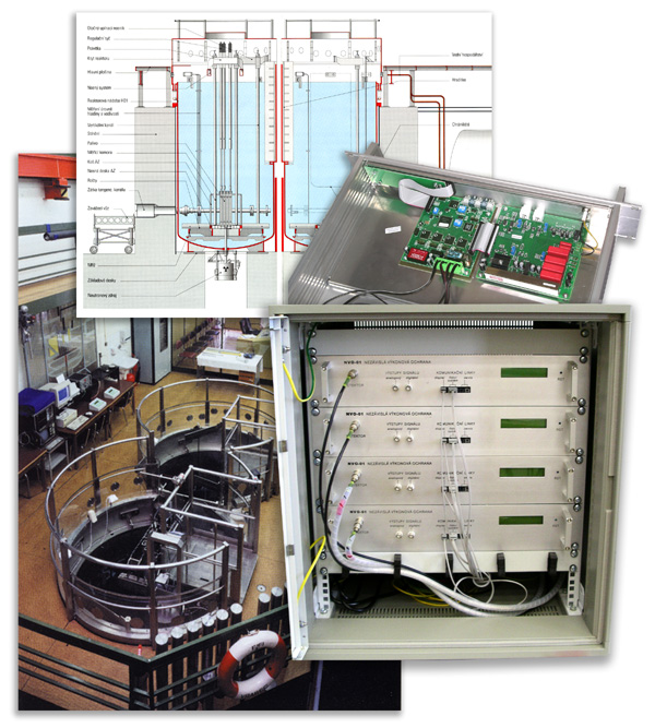
TEDIA® was cooperating in rebuilding of the VR-1 (research nuclear reactor) control system with a general technology supplier SKODA JS a.s..
TEDIA® was ensured the development and manufacturing of the independent power protection (IPP) units including most of the firmware and the converters for communication via fibre optics.
The system of IPP represents a part of the control system, which is required to be the most reliable in the whole structure. The task of IPP is to ensure the power safety limits of the nuclear reactor in the event of failure or even malfunction of the operational power measurement (OPP).
The unit was realised using the most modern electronic components (low-noise amplifiers for processing of the input signal of tens of microvolts, stabilized low-noise high voltage power supplies, powerful MCUs and CPLD/FPGA gate arrays) and fully redundant circuitry.
Sometimes we develop a bit simpler equipments...
Three axes amplifier for IEPE sensors (2017)
For conditioning signals IEPE sensors (ie. Integrated Electronic Piezoelectric) to unified voltage range inputs was designed a quite simple board.
The board contains three independent channels, each equipped with a current source 4 mA with sensor terminals voltage up to 22 V.
Input signals are processed by low-pass filters (threshold frequency 2 Hz approx.) and then by high-pass filter (threshold frequency 10 kHz approx.). Finally, signals are amplified by amplifiers with differential outputs with voltage range ±10 V. All parameters can be widely modified by replacing components.
The power supply circuits were designed as isolated from the signal section, so almost any available power supply can be used without the risk of interference of the measured signals. The board is intended for installation in the housing.
For encapsulation amplifier board could be used Hammond 1455C801 type housing.
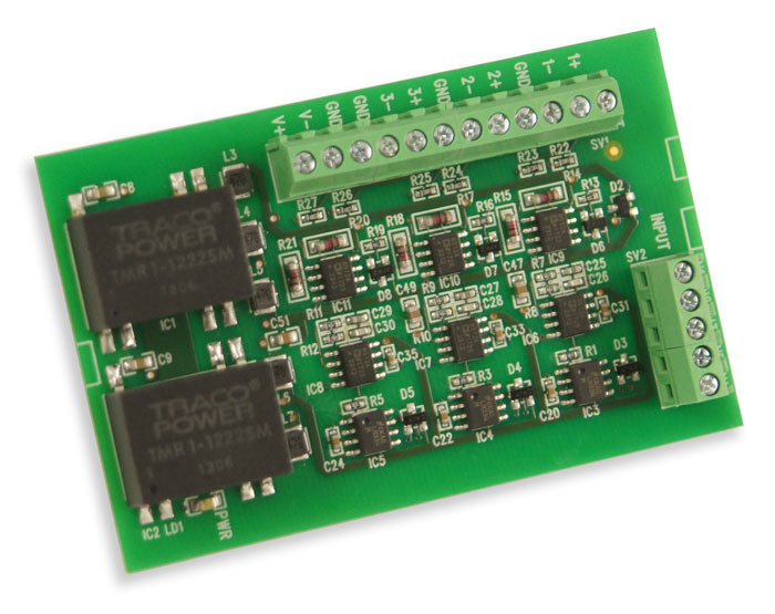
Ultrasonic ceramic transducers amplifier (2017)
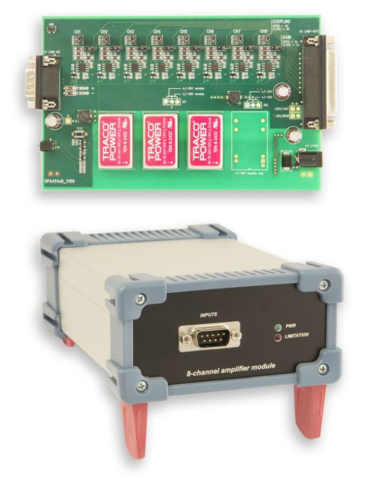
The ultrasonic ceramic transducer amplifier was developed especially for research purposes within a university project ongoing at University of South Wales, Faculty of Computing.
The board contains eight independent amplifiers with voltage range up to ±40 V and continuous current up to 50 mA. Frequency bandwidth is limited by LPF at 1 Hz (optionaly 0 Hz when filter is turned off), upper threshold frequency depends of the choiced type of amplifier (more then 50 kHz at full signal amplitude).
Amplifiers are protected against short circuit at the outputs, moreover current limiting and thermal protection are provided (malfunction is indicated by LED on the front panel).
The power supply circuits were designed as isolated from the signal section, so almost any available power supply can be used without the risk of interference of the measured signals.
The amplifier board was built into an aluminum case that provides sufficient heat dissipation.
Analog isolation amplifier (2011)
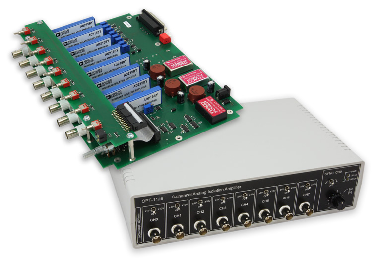
The eight-channel isolation amplifier was developed especially for measuring of detonating effects in the Physical-Technical Testing Institute s.p.. The amplifier also provides circuitry for the measured signal trigger.
All independently isolated channels provide input amplifier with programmable gain and bandwith of more than 100 kHz. The output signals in the range of ±10 V are processed and analyzed by the PCI measuring card and the ScopeWin32 software.
Electronics for the Gas Concentration Detectors (2008)

The control electronics for the gas concentration detector (especialy carbon dioxide) was developed for KR Protect, spol. s r. o., a leading company dealing with components for detection of combustible, explosive and toxic gases and fumes.
The electronics processes the signal from the electrochemical gas sensor (both fitted in a massive metal case). The signal is digitized by ADC, then proccessed by a microcontroller (configurable linearization and calibration) with the 4-20mA current loop output signal. The microcontroller also analyses exceeding of the set of limits after a certain period of time, activating the output relay if exceeded.
The detector configuration can be realised using the serial communication interface or the built-in buttons.