
MU-615
The MU-615 module is designed for resistance measurements and offer six analogue input channels configurable in two-wire, three-wire and four-wire topology.
For direct measurement with different temperature sensors (RTD´s), the firmware implements algorithms for linearization of most of the resistive thermometers.
Just like other MicroUnit modules, MU-615 allows to choose an appropriate input range (including thermocouple and RTD linearization) independently for each input channel.
The module is based on 24-bit A/D converter, high precision and long-term stability is achieved by the autocalibration running continuously on the background of cyclic measurements. The time needed to measure all channels, including autocalibration and open senzor detection, takes less than 1.8 seconds. Alternatively, floating filters averaging the results of the ten most recent measured values can be activated.
The module also includes two digital inputs with counter capability and two digital outputs.
The whole analogue input group is isolated from other circuits of module (DIO ports, power supply and RS-485 interface), but inputs are not isolated from each other. The digital inputs and outputs are isolated from other circuits and from each other.
Specifications
| Type | MU-615 |
|---|---|
| Analog inputs | 6x R/RTD |
| Analog input topology | four-wires three-wires two-wires (software compensation of wire resistance) |
| Resistance ranges | 4kΩ 2kΩ 1kΩ 500Ω 250Ω 120Ω |
| Excitation current | 0.25mA approx. |
| Internal temperature sensor |
-40÷70°C |
| ADC resolution | 24-bit (continuous offset and range autocalibration) |
| Basic accuracy | better than 0.1% of FSR (U/R ranges) better than 1°C of FSR (temperature sensor) |
| RTD linearization | Pt100/3850 (-200÷850°C) Pt100/3911 (-200÷850°C) Pt500/3850 (-200÷850°C) Pt500/3911 (-200÷850°C) Pt1000/3850 (-200÷850°C) Pt1000/3911 (-200÷850°C) Ni100/5000 (-60÷250°C) Ni100/6180 (-60÷250°C) Ni1000/5000 (-60÷250°C) Ni1000/6180 (-60÷250°C) KTY10-5 (-50÷120°C) KTY10-6 (-50÷120°C) KTY10-62 (-50÷120°C) KTY10-7 (-50÷120°C) |
| Measurement period | less than 1.8s (the time needed to measure all channels) |
| Overvoltage protection | ±15V continuously (±20V max. 1s) |
| Analog input isolation | 1kVDC (AIN block against other circuits) |
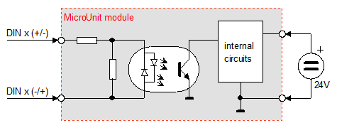
| Number of digital inputs | 2 |
| Type of digital inputs | isolated, bipolar 24V with 50Hz filter |
| Digital input signal (level L) |
<3VDC (both polarities) <3VRMS (signal 50Hz) |
| Digital input signal (level H) |
10÷35VDC (both polarities) 15÷35VRMS (signal 50Hz) |
| Overvoltage protection | ±60VDC (max. 1s) 60VRMS (signal 50Hz, max. 1s) |
| Digital input impedance | 14kΩ approx. |
| Digital input isolation | 1kVDC (DIN block against other circuits) 100VDC (between DIN channels) |
| Number of counters | 2 |
| Counter frequency | 10Hz max. (signal asymmetry 40/60% max.) |
| Counter range | 0÷4294967295 (i.e. 32-bit counter) |
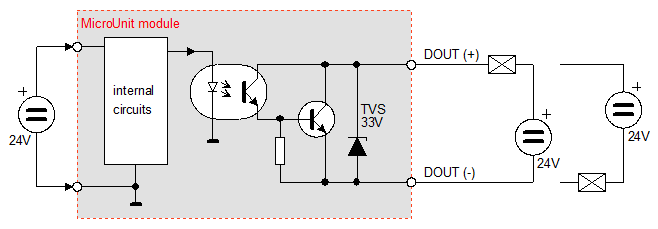
| Number of digital outputs | 2 |
| Type of digital outputs | isolated, 24V |
| Digital output signal | 32VDC/0.3A max. |
| Digital output isolation | 1kVDC (DOUT block against other circuits) 100VDC (between DOUT channels) |
| Supply voltage | 10÷30VDC |
| Power consumption | 2W max. |
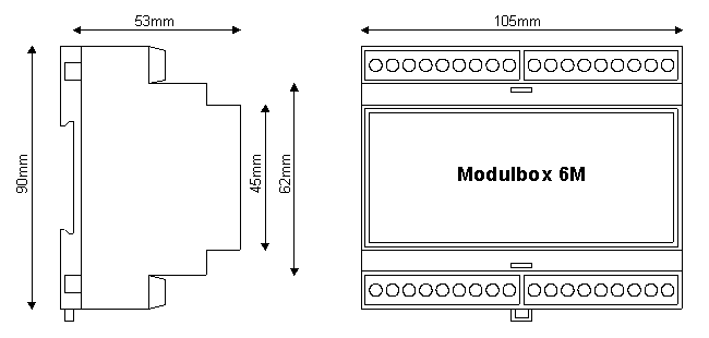
| Housing & Dimensions | Modulbox 6M |
| Signal terminals | screw terminals wire 1.0mm2 max. (analog input signals) wire 2.5mm2 max. (all atoher signals) |